good-to-know
A brief guide: Turbine center frames
Turbine center frames are sophisticated engine components. AEROREPORT explains what they do and highlights the innovative technologies that lie behind them.
Author Isabel Henrich, Tobias Weidemann | 4 mins reading time published on: 01.08.2023
Author
Isabel Henrich
studied political science and communications. At MTU, she coordinates the editorial process of AEROREPORT and is responsible for the conception and development of its content.
Tobias Weidemann
has been working as a journalist and content consultant for more than 20 years. He writes about technology and business topics, often with a focus on business IT, digitalization and future technologies.
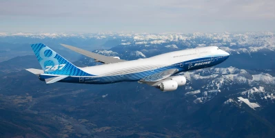
MTU develops and manufactures turbine center frames (TCFs) for engines that power long-haul airliners. The company’s Munich site and MTU Aero Engines Polska produce TCFs for the GP7000 (Airbus A380), the GEnx (Boeing 787 Dreamliner and Boeing 747-8) and the GE9X (the exclusive engine for the Boeing 777X).
You may also be interested in following content
What the turbine center frame does in the engine
Turbine center frames serve as a duct for the hot gas flowing from the high-pressure turbine into the low-pressure turbine. They have to fulfill a variety of tasks: their function is to route the flow of hot gases exiting the high-pressure turbine at a temperature of more than 1,000 degrees Celsius to the low-pressure turbine while keeping aerodynamic losses to a minimum. Both turbines need to be provided with cooling air, which is supplied through the turbine center frame. As the supporting structure, the TCF accommodates the rear bearing of the high-pressure spool, thus playing a major part in maintaining the clearances in the high-pressure turbine. At the same time, it is essential to ensure seamless delivery and return of oil through the hot structure. Moreover, the TCF must be capable of withstanding extreme loads that could act on it—in the event of a fan blade out, for example.
So during operation, TCFs are exposed to extreme stresses such as high mechanical loads and high temperatures. Since TCFs have to fulfill a variety of tasks, the requirements for manufacturing accuracy and the circumferential symmetry are exacting.
Masterpiece for the GE9X
In July 2014, MTU assumed responsibility for the development, production and maintenance of the TCF in the GE9X. This engine will exclusively power the Boeing 777X starting in 2025, and it will be the most efficient engine ever launched by GE in terms of fuel consumption to thrust ratio. The GE9X TCF is MTU’s most technologically sophisticated turbine center frame.
Innovative technologies in the GE9X TCF
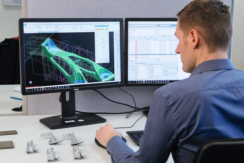
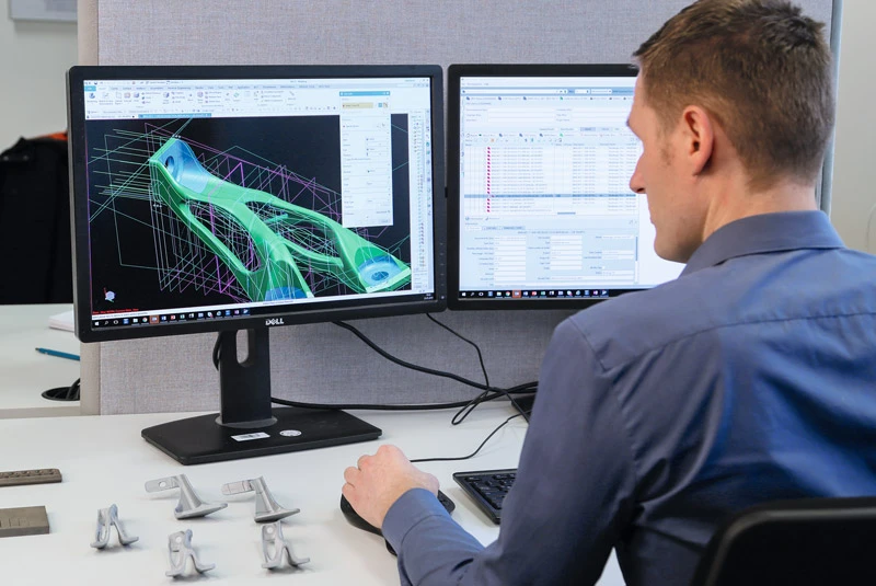
Building on the basic architecture of the GEnx TCF, the GE9X TCF features extensive optimizations that further improve its weight, service life and manufacturability. Among other things, construction methods were optimized by way of additive manufacturing. It also features MTU’s first fully bionically designed components: brackets for oil lines. These achieve a weight reduction of 35 percent. The GE9X has three of these brackets per engine.
Future developments
MTU is already conscientiously preparing for further possible TCF applications: work is underway to further improve the aerodynamic design and to better understand the temperature distribution on the component surfaces, taking into account cooling air flows.
In close collaboration with GE, detailed experimental investigations were carried out at Graz University of Technology on a test stand set up specifically for this purpose. This data is used to validate simulation models, which are then employed for future designs. From this, more precise statements can be made about the service life of these complex and highly stressed components, with a view to achieving increased robustness.
Manufacturing at its best
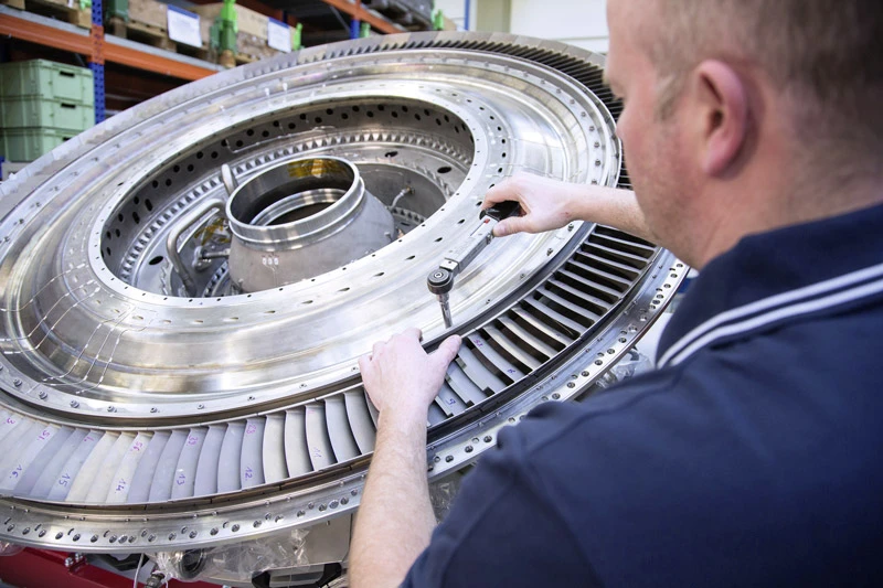
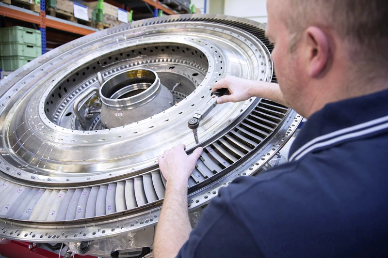
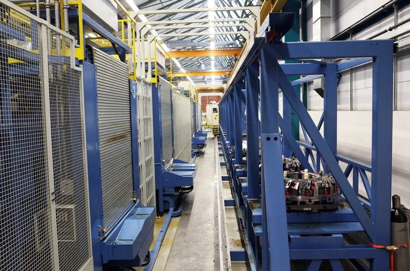
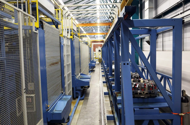
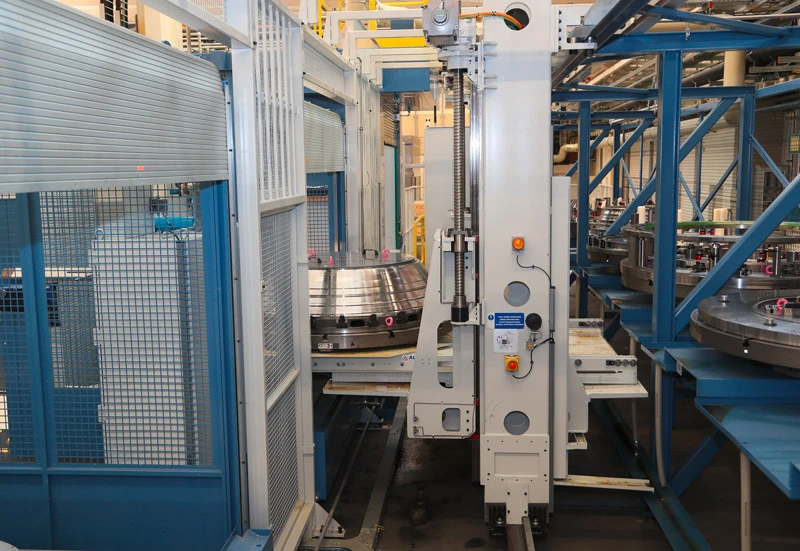
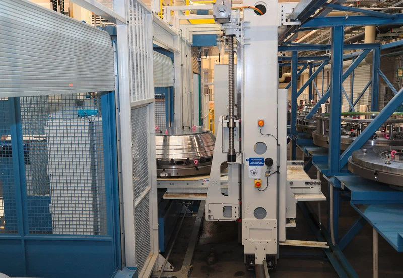
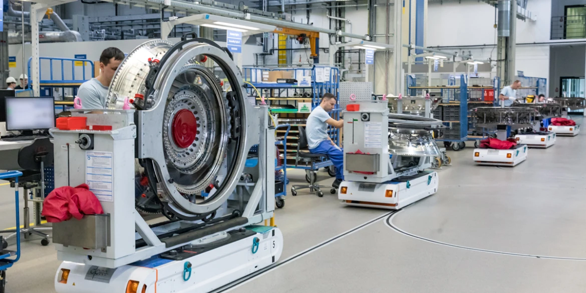
A TCF consists of three modules: the accessories, the hub strut case (HSC) and the flow path hardware (FPH). MTU manufactures the FPH—the cast components that form the gas supply channel—at its Munich site on a production line made up of a total of eight tool machines, each capable of processing, milling, grinding and drilling with an extremely high degree of customization. Each machine is supplied with workpieces and tools with the help of largely automated loading. Most of these machines can be used to manufacture any of the required components, which means the line operates at maximum capacity.
The TCF production line uses six-axle tool machines featuring an integrated tool exchange system and suitable measurement technology. First, a transport vehicle brings each of the tools to the relevant machine, where they are fed into the buffer. This buffer is divided into two sections, one for workpieces, the other for tools. Loading is done either manually or, in the case of large heavy items, with the help of a loading system. Workpieces are transported to the workroom for processing. If the buffer is loaded, the machine performs an identification maneuver to detect all the items present.
All processing steps on a single machine
Next, the workpieces are aligned in the machine and the correct tool for processing them is provided. The tool processes the workpiece according to the prescribed steps and generates the corresponding process data. As soon as the machine finishes one workpiece, it moves on to the next. The sequence of steps depends on the priorities set by the workshop based on the delivery conditions.
In this way, the machines can work autonomously for extended periods according to the prescribed workflow—until either the required tool is unavailable or until all components are finished and all orders completed. Only if one of the workpieces or tools required to complete the next step is missing will the production line call for a human operator.
Outlook: Highly automated production
The next generation of machines is to be even more automated: with an adequate supply of material, components could pass between differently tooled machines for an extended period. This would increase the efficiency of such production systems and pave the way for significantly longer automated production phases.
This kind of innovation is both required and reasonable—not just in terms of technological advancement, but also because turbine center frames are becoming larger all the time. In addition to being the largest commercial engine GE makes, the GE9X poses new challenges on the manufacturing process: today’s standard TCFs have a diameter of around 1.5 meters, but the one in the GE9X is even bigger than that.


